Ensuring Product Safety in Hazardous Areas with Intrinsic Safety
Content of This Article
Ensuring Product Safety in Hazardous Areas with Intrinsic Safety
Special care must be taken when using electrical appliances in potentially explosive atmospheres. The safety of workers and systems has top priority. A proven and flexible protection method to ensure the safety of products used in hazardous areas is the intrinsic safety type of protection. Corresponding product safety standards regulate the safe operation of devices in potentially explosive atmospheres. These standards define limit values for parameters, known as entity parameters, such as voltage, current, and capacitance, which ensure the safe operation of devices in hazardous areas. In this context, control drawings illustrate how the components within these safety parameters are interconnected, which is critical for compliance and operational integrity.
Learn more about the standards, area classifications, parameters, and their interrelationships for an intrinsically safe circuit.
What Product Safety Standards Are Related to Intrinsic Safety?
The criteria and the specific conditions for the intrinsic safety type of protection are described in the product safety standards that cover this protection concept. The main global standard detailing the design and testing of intrinsic safety is IEC 60079-11. In the US and Canada, this IEC standard is adopted with some modifications known as national deviations. The national adoptions are UL 60079-11 for the US and CSA 22.2 No 60079-11 for Canada. To further explain this concept of protection, it is important to know that an apparatus must meet certain design criteria that take into account not only normal operation, but also failures within the product to ensure safety.
Meeting and Understanding the Specific Criteria and Area Classifications of Intrinsic Safety
There are many design elements within each device that need to meet the specific criteria of the standard to assure both electrical spark ignition safety and thermal ignition source safety. An intrinsic safety evaluation within the apparatus can be very complicated and detailed, and often the devices contain additional circuitry for the sole purpose of providing needed protection for intrinsic safety. It is not sufficient for the device to only operate at low voltage and current. For example, sensors that comply with the NAMUR standard operate at very low voltages and currents, but this does not automatically make them intrinsically safe and suitable for use in a hazardous location.
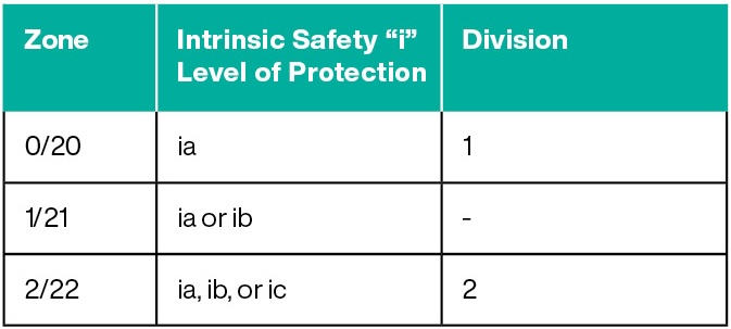
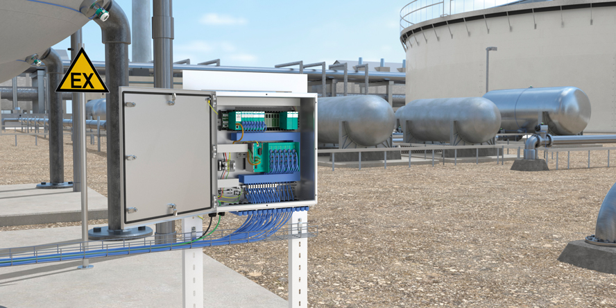
When planning applications in hazardous areas, it is therefore important to understand the area classification in which the intrinsically safe apparatus is to be installed and to select one that is properly certified for use in this location. It is equally important to properly interface this intrinsically safe apparatus to a suitable associated apparatus to maintain safety. The associated apparatus must also be properly certified for use in an intrinsically safe circuit for the area classification of the end application.

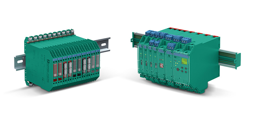
To connect an intrinsically safe field device to the control system, an intrinsic safety barrier is usually required, which limits the energy fed into the circuit and isolates the intrinsically safe circuit from the non-intrinsically safe circuit. Intrinsic safety barriers such as Zener barriers or isolated barriers ensure safe signal transmission and are associated equipment.

The proven K-System intrinsic safety barriers from Pepperl+Fuchs ensure safe signal transmission in hazardous areas.
Evaluation and Proof of Intrinsic Safety
The proof of intrinsic safety or an intrinsically safe circuit is provided by calculation. For this purpose, the values for voltage, current, and power as well as the energy storage devices, including cables and connecting wires, are assessed with their capacitances and inductances.
Understanding Entity Parameters for Intrinsically Safe Apparatus and Associated Apparatus
Most equipment on the market, both intrinsically safe apparatus and associated apparatus, are certified with published intrinsically safe parameters, also known as entity parameters. These parameters allow the safe combination of an intrinsically safe apparatus and an associated apparatus to form the final intrinsically safe circuit. In the US and Canada, these details along with other relevant installation information are specified in a drawing known as the control drawing, and the marking on the device refers to it. The control drawing is required to be available prior to sale of the device so that an intrinsically safe circuit can be confirmed during the design phase.
For the associated apparatus, the basic entity parameters are:
- maximum open circuit voltage, Uo (Voc)
- maximum short circuit current, Io (Isc)
- maximum power out, Po
- maximum capacitance that can be connected, Co (Ca)
- maximum inductance that can be connected, Lo (La)
For the intrinsically safe apparatus, the basic entity parameters are:
- maximum input voltage, Ui (Vmax)
- maximum input current, Ii (Imax)
- maximum input power, Pi
- maximum capacitance at the terminals, Ci
- maximum inductance at the terminals, Li
The Entity Parameter Concept: Voltage, Current, and Power
The first set of comparisons are made with voltage, current, and power. For the intrinsically safe apparatus or field device, Ui (Vmax), Ii (Imax), and Pi were used as the maximum values allowed at the input terminals during the certification evaluation. As the safety analysis is based on these values not being exceeded, the connections from the associated apparatus to the intrinsically safe apparatus must also be limited based on criteria within IEC 60079-11. As part of the analysis of the output of the associated apparatus, the published values Uo (Voc), Io (Isc), and Po have been determined as the maximum voltage, current, and power are known. So, if we confirm that Ui ≥ Uo, Ii ≥ Io, and Pi ≥ Po, we know that the associated apparatus cannot deliver more energy than the intrinsically safe apparatus is designed to handle and the safety of the intrinsically safe apparatus is maintained as far as these entity parameters are concerned. This leaves us with the question of the capacitance and inductance of the circuit.
Capacitance and Inductance in Intrinsically Safe Circuits
The ability of a capacitance to quickly supply current and an inductor to quickly supply voltage affects the overall safety of an intrinsically safe circuit, therefore these energy storage elements need to be limited to maintain the safety of the circuit. This is where Co, Lo, Ci, and Li come into the assessment, but also the cable or the connecting wires. The connecting cable has a characteristic capacitance per unit length and a characteristic inductance per unit length. These values are often referred to as Ccable or Cc and Lcable or Lc in control drawings. The datasheets for the cable likely refer to the capacitance and inductance as a characteristic impedance, with units in F/m and H/m. If these values are not known, many control drawings give an indication of common values associated with typical single twisted-pair cables.
The evaluation that needs to be carried out to ensure safety for the capacitance and inductance is Co > (Ci + Ccable) and Lo > (Li + Lcable). This requires the total length of the cable from the associated apparatus to the intrinsically safe apparatus to be known so the total Ccable and Lcable can be determined. However, there may be a catch to this simple assessment. The control drawing of the associated apparatus may contain further information on the reduction of the Co and Lo values for situations where both Ci and Li are greater than 1% of the value of Co and Lo. This reduction factor is often referred to as the 50% rule. The details of this are beyond the scope of this blog article, we mention it here only to bring it to your attention. Once this evaluation has been made for a particular circuit loop, most installation sites require the components and calculations to be documented in a document known as a descriptive system document, which will be used as a reference for initial signoff and subsequent audits and maintenance work to ensure the safety of the circuit and the entire installation.
Summarized: When Is a Circuit Considered Intrinsically Safe?
Intrinsic safety is a specific type of protection and not a general term for equipment designed for use in a hazardous location. The basic principle of intrinsic safety is to limit energy in order to eliminate potential ignition sources. The energy available for the operation of an electrical or electronic device is therefore limited, so that electrical sparks or thermal ignition sources do not pose a hazard. A circuit is considered intrinsically safe if the value pairs of voltage and current are below the relevant ignition limit curve for the explosive atmosphere. When used in Zones 1 or 0, the permissible value is additionally reduced by a safety factor of 1.5.
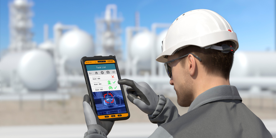
Common examples of intrinsically safe apparatus are sensors, actuators, and mobile devices such as handhelds or intrinsically safe smartphones and tablets. The intrinsically safe apparatus and the associated apparatus are the two main components of an intrinsically safe circuit installation. Most are certified according to the entity concept, which provides the designer with a simple method for evaluating the safety of the completed intrinsically safe circuit. In the US and Canada, there is a required document, known as a control drawing. The intrinsically safe circuit can be confirmed by correctly matching the entity parameters. A descriptive system document details all components, connections, and calculations associated with each intrinsically safe circuit within the system for initial signoff and subsequent audits and maintenance.

We hope this blog article has given you more confidence in using intrinsic safety on machinery and in process applications. Intrinsic safety is an excellent protection method and is well worth familiarizing yourself with when designing for hazardous areas. As there is much more to say and explain about intrinsic safety than can be accommodated in this blog article, we encourage you to learn more through the Pepperl+Fuchs compendium on intrinsic safety, which you can find in our Electrical Explosion Protection Knowledge Base.
More Information
Subscribe to our newsletter and receive regular news and interesting facts from the world of automation.
