How is a type code from Pepperl+Fuchs structured?
Content of This Article
How Is a Type Code from Pepperl+Fuchs Structured?
Our product portfolio of thousands of sensors includes: inductive, capacitive, magnetic field and ultrasonic sensors as well as sensors for special applications. To help you find the right sensor for your applications, we explain below how a type code from Pepperl+Fuchs is composed.
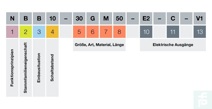
Type codes from Pepperl+Fuchs are composed of three categories for the above sensors:
In the first category, a distinction is made between functional principles (sensor type), application-specific features (type of use), installation situation (flush/non-flush) and the sensing distance.
In the second category, a distinction is made between the size of the thread, the design, the material, the thread length and option 1 (angled/swivel transducer).
The third category summarizes the electrical outputs. A distinction is made here between the electrical output, the special properties (e.g. whether the output is pressure-resistant/weld-proof), option 2 (e.g. whether the sensor is IO-Link-capable) and its connection.

The first category is explained in more detail below
- Operating principle
All Pepperl+Fuchs sensors are listed under the category “functional principle,” where the first letter of the type code symbolizes a defined sensor type. For example, the letter “U” stands for “ultrasonic sensor” and the letter “N” for “inductive sensor.” - Series-specific application features
When selecting a sensor, it is important to determine where and how the sensor will be used. Under the category “application-specific features,” you will find the different application areas of sensors with their type descriptions. For example, the UC6000 ultrasonic sensor can be used for water rides, since neither dirt nor water impairs the function of the comfort series (C). - Installation situation
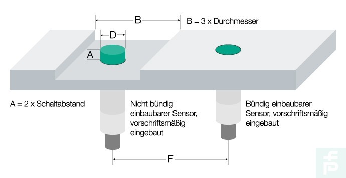
For inductive and capacitive sensors, a distinction is made between flush and non-flush mounting. Here, non-flush mount sensors achieve the largest possible sensing distance (based on the diameter of the active area).

Flush Mount Versus Non-flush Mount
1. Non-flush mountable sensors
An inductive sensor uses coils to generate electromagnetic fields. To achieve a forward direction of the field, the coils are embedded in a shell core. Despite these measures, part of this field is radiated laterally and influenced by surrounding metal. Such a side effect can also be observed in capacitive sensors. To prevent sensors with a high range from being damped by surrounding metal, a free space must be created around the sensor element. The size of this clearance can be found in the technical data of the respective sensors.
2. Flush mountable sensors
Flush mount sensors can be used without clearance (A=0). The resulting advantage over a non-flush mount sensor is that they are better protected and less sensitive to false interference. One disadvantage, however, is the small sensing distance, since the active surface of the sensor is already surrounded by metal. The lateral influence by the surrounding metal is reduced by a special internal shielding. This is done at the expense of range. These sensors achieve only approx. 60 % of the switching distance of non-flush versions.
3. Flush mounting capacitive sensor
For capacitive sensors, Pepperl+Fuchs provides specially balanced, flush mountable sensors (CJ,CBB,CCB types). Sensors in cubic housings are generally mounted on a carrier material. In this case, dimension A is defined by the height of the housing. A special quality feature of capacitive sensors is their shielding against the carrier material. The critical case arises when installed in metallic conductive carrier material. Pepperl+Fuchs sensors can be installed in any substrate material under the above conditions.
Switching distance
Inductive Sensors
The switching distance is the most important parameter of a proximity switch. It depends mainly on the sensor diameter (coil or capacitor). The dimensions and material composition of the actuator as well as the ambient temperature have an additional influence. For magnetic proximity switches, the orientation and field strength of the magnet used must also be taken into account.
Magnetic field sensor
The achievable sensing distance of a magnetic field sensor depends on the size and the magnetic flux density of the actuating magnet. The DM60 permanent magnet is used as a reference value for determining the nominal operating distance (Sn). The magnet has a diameter of 31 mm and a height of 15 mm with a remanence Br of 380…400 mT. A polarity-dependent response curve of the sensor results when the sensor surface is passed over laterally. Thus, a bipolar orientation of the magnet results in a two-hump response curve. Unipolar alignment of the magnet results in a central sensing area with lateral side humps. These side humps are responsible for the fact that a certain minimum distance between the magnet and the sensor should be maintained for a reliable switching procedure.
Summary
Type codes from Pepperl+Fuchs are composed of three sections, each of which provides more detailed information about the sensor, its design and its electrical outputs. The first section (first four characters) contains information about the operating principle (sensor type), its application-specific features (application type), the installation situation (flush/non-flush) and the sensing distance of a sensor. If you have any questions about our type code, our experts are always at your disposal.
More Information
Subscribe to our newsletter and receive regular news and interesting facts from the world of automation.
