8 Advantages of IO-Link
Content of This Article
IO-Link: 8 Advantages Simply Explained
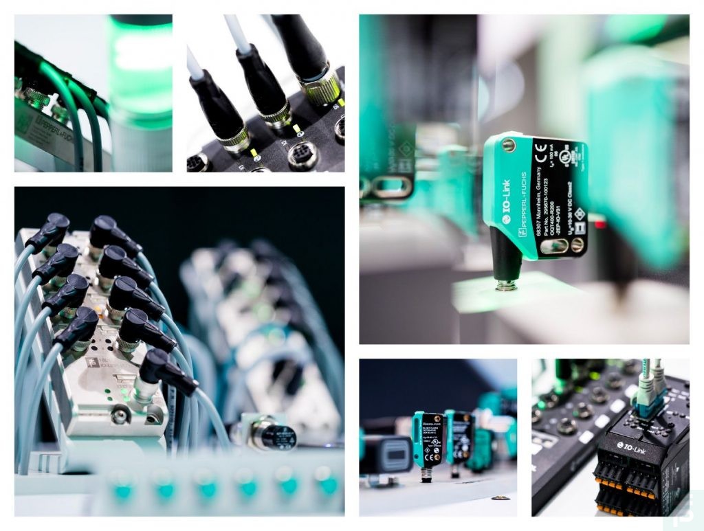
As a communication protocol, IO-Link is now a recognized standard in virtually all industries. The microcontrollers used make the sensors even more intelligent and can provide additional information about the device status or signal quality as well as store parameter settings. This makes it very easy to replace defective sensors, as new sensors can automatically adopt the stored settings during operation. In addition, IO-Link can be integrated into any network independently of the fieldbus via a point-to-point connection and standard 3-wire cabling. Mixed operation of IO-Link and conventional switching signals with identical wiring is also possible via an IO-Link master. Another advantage – IO-Link sensors can also be connected to conventional digital inputs. Read more about these and other advantages of IO-Link in our blog post …
1. IO-Link system
IO-Link is a communication standard for intelligent sensors and actuators for connection to an automation system. An IO-Link system consists of a point-to-point connection between an IO-Link device and an IO-Link master. The IO-Link master establishes the connection between the IO-Link devices and the automation system.
For the user, this results in advantages such as: Data storage, remote parameterization, extended diagnostics and reduced cabling.
2. Data Storage/Parameter Server
Parameters can be stored within the IO-Link master, which enables the automatic configuration of IO-Link devices. This makes it possible to quickly and easily replace failed or damaged sensors (as of IO-Link 1.1), which reduces downtime and maintenance costs.
Example: One company installed IO-Link 1.1 sensors and activated data storage on the corresponding master ports at the time of installation. If an IO-Link device needs to be replaced, the same type of device can be connected and automatically configured from the master port with the appropriate parameters.
3. Configuration and Parameterization
Configuration tools are required for setting up an IO-Link system. IO-Link configuration tools from master manufacturers can read IODDs. The most important tasks of IO-Link configuration tools are:
- Assigning the devices to the master’s ports
- Assigning addresses (I/O addresses of the process data) to the ports within the address range of the master
- Parameterizing IO-Link devices
Connected devices can also be diagnosed. IO-Link configuration tools provide a clear representation of the IO-Link system down to the field level.
4. Various Types of Data
Three types of data are available with IO-Link: process data, service data, and event data.
- Process data/cyclical data
Process data is information (e.g., temperature, distance, etc.) that a device should supply or measure. - Service data
Service data is not related to process data and is also referred as acyclic data (manufacturer, model number, etc.). - Event data
Event data consists of notifications or indicators that are created when a critical event occurs. Examples of event data: incorrectly connected sensor, communication error, or open circuit.
5.IODD: IO Device Description
The IODD file (IO Device Description) is available as device description for each device. This file can be found either on the manufacturer’s page or on IODD.
The IODD provides a wide range of information for system integration: communication properties, device parameters with value range and default value, identification, process and diagnostic data, device data, text description, image of the device, manufacturer’s logo. The IO-Link configuration tools of the master manufacturers always display the structure of the IODD in the same way.
6. Reduced/Simplified Wiring
There are a number of ways in which IO-Link offers reduced or simplified cabling:
- By using unshielded 3- or 5-wire standard cables
- By using an IP67 master, which requires less space in control cabinets and reduces wiring time
- By using digital and analog data collectors—so-called I/O hubs—which reduce the time needed to wire the inside and outside of the control cabinet
7. Device Validation
Device validation allows the user to choose whether a port on the IO-Link master works with any sensor or only with a specific type of sensor. Validation can be set down to the serial number.
Use case: If a system programmer only wants distance sensor 1 to work on port 1, this can be achieved with device validation. This prevents possible errors and communication problems during regular maintenance. If a device is connected incorrectly, a red LED on the master lights up and the master will not establish permanent communication with the device.
8. ISDU: ISDU: Index Service Data Unit
Process data is transferred cyclically to or from the IO-Link device via the fieldbus. The parameter data, on the other hand, must be explicitly transferred from or sent to the PLC. The ISDU (indexed service data unit) was defined in the IO-Link specification for this purpose. There are several ways to read/write ISDUs via interfaces and clients like a PLC. Each message can contain a single command, multiple commands with the same data area size, or commands with different data area sizes. ISDUs simplify programming and offer more possibilities for configuring devices during operation.
User benefits: Simplifies programming while providing more options for configuring devices on the fly.
Subscribe to our newsletter and receive regular news and interesting facts from the world of automation.