ASi-3, ASi-5, and IO-Link: A Comparison of Three Communication Protocols
Content of This Article
ASi-3, ASi-5, and IO-Link: A Comparison of Three Communication Protocols
When using modern automation systems in industry, the focus is not only on technical performance, but also on cost-effectiveness. Ideally, such systems combine high functionality, flexibility, and reliability—at the best possible price. As simple and comparatively cost-efficient wiring technologies for sensors and actuators in the field, AS-Interface (ASi) and IO-Link meet precisely these requirements.
How exactly do these subordinate communication systems work? And what makes the ASi-3 and ASi-5 generations and IO-Link so special? In this blog article, we answer these questions and highlight application areas where the technologies best demonstrate their strengths.
AS-Interface: Functionality, Advantages, and Disadvantages
What Is AS-Interface and How Does It Work?
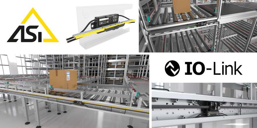
AS-Interface, short for “Actuator Sensor Interface”, is an internationally standardized communication standard (IEC 62026-2) that is used for wiring sensors and actuators at the lowest automation level. With AS-Interface, both the power supply and data transmission are carried out via a single reverse polarity protected, yellow flat ribbon cable. Using piercing technology, ASi devices can be easily and flexibly attached along the entire flat ribbon cable and repositioned at any time.
In the ASi 3 standard, a master communicates cyclically with the participants, also known as ASi nodes, whereby each participant is queried with 4 bits of bidirectional IO data per cycle. An ASi master can transmit data and energy to up to 62 devices at a system voltage of 30.5 V. Devices with higher power requirements are supplied with 24 V or 48 V via a separate flat ribbon cable. A major advantage is that ASi can be used in a free topology as a tree, star, line, or ring structure. The free topology makes setup, modularity, granularity, and installation easier for the user. The system can also be flexibly expanded at any time.
Advantages and Disadvantages of ASi-3
Compared to conventional parallel wiring of sensors and actuators, the wiring effort is significantly reduced by using AS-Interface. As IO components are conveniently connected using piercing technology and both safe and non-safe signals are transmitted on the same cable, assembly work and installation costs are reduced to a minimum. ASi-3 can also be used to transmit analog values in several cycles; however, ASi-3 is not suitable for communicating larger data volumes of more than 2 bytes. ASi-3 is therefore a cost-effective, particularly rugged solution for simple sensors and actuators.
Differences Between ASi-5 and ASi-3
In 2007, a consortium of originally eight companies initiated the development of a new AS-Interface generation in order to take the idea of Industry 4.0 into account. The verification and chip development took many years and was not able to fulfill all the functions required at the time—including the tunneling of IO-Link data and the goal of achieving the ruggedness and cost-effectiveness of ASi-3.
Even though ASi-5 uses the familiar flat ribbon cable, the communication has been completely redesigned. While ASi-3 is based on the master-subscriber principle with a carrier frequency of 167 kHz, ASi-5 uses parallel communication to all ASi-5 subscribers with transmission frequencies of 1–10 MHz. Due to the higher frequencies of ASi-5, reflections can occur more easily at the open end of the line, leading to constructive and destructive interference. The signal level of ASi-5 is <100 mV, which makes it significantly more susceptible to external interference compared to ASi-3 with +/- 3V signal level.
Like its predecessor, ASi-5 communicates over 200 m strand length. Unlike ASi-3, however, the line length cannot be extended to 600 m with up to two repeaters in series. With a four times higher data bandwidth per cycle, users with ASi-5 have up to 16 bits per subscriber at their disposal. In contrast to ASi-3, there are very few suppliers of individual components for ASi-5 and only one system provider. ASi-5 is therefore considered a niche product with a single source.
Integration Limits with Other Technologies
Where previously 62 users could be connected, ASi-5 now enables the integration of up to 96 users. With ASi-5, cycle times of 1.27 ms can be achieved for 24 subscribers. Due to the larger data bandwidth of 16 bit, ASi-5 can transmit analog values faster. However, if parallel operation with ASi-3 devices takes place, the number of devices is reduced to a total of 62 ASi-3 and ASi-5 devices. This is due to the inductive and capacitive load on the network.
In contrast to ASi-3, the data image for ASi-5 is not permanently defined and cannot simply be transferred to the control level (PLC) due to the scope. Special configuration software is required for this.
The integration of IO-Link into an ASi-5 network is only possible to a very limited extent and only makes sense in exceptional cases. Routing an IO-Link device with up to 32 bytes of data bandwidth via ASi-5 with 2 bytes of bandwidth leads to performance limitations of IO-Link. Only six IO-Link devices with 32 bytes (192 Bytes) would completely occupy the ASi-5 communication (96 x 2 bytes = 192 Bytes) without limiting performance. In addition to overloading and slowing down communication, there are further disadvantages due to increased jitter times. As it was not possible to implement IO-Link tunneling with ASi-5, it is necessary to integrate a comparatively expensive IO-Link master into the ASi-5 module. As a result, the transparency and continuity of IO-Link, which are considered important advantages of IO-Link technology, are lost.
ASi-5 is therefore designed for complex sensor technology, fast cycle times and a high data throughflow. This includes, for example, very complex combinations of digital and analog modules with safety functions or modules with 16 I/Os, which rarely occur in practice.
Due to the limitations mentioned above, the comparatively high costs, and the complexity of the technology, Pepperl+Fuchs has completely discontinued the development of the ASi-5 system.
IO-Link: Functionality, Advantages, and Disadvantages
What Is IO-Link and How Does It Work?
As a globally standardized, manufacturer-independent communication technology for sensors and actuators, IO-Link is standardized in accordance with IEC 61131-9 and compatible with all common fieldbuses. Using an unshielded three-wire standard cable, even the simplest sensors and actuators can provide identification and diagnostic data across the entire system structure in addition to switching signals.
For this purpose, a connection up to 20 meters long can be established between an IO-Link device and the IO-Link master. The IO-Link master is either located in the DCS cabinet or is installed directly in the field. From there, it establishes the connection or communication between IO-Link devices and the automation system. A master can have several IO-Link channels, so-called ports, to each of which an IO-Link device can be connectedꟷa sensor, actuator or RFID read/write device, for example. IO-Link is therefore not a bus system, but a pure point-to-point connection. In so-called SIO mode, short for standard input-output, a sensor transmits its detection status as a 0 V and 24 V signal. As soon as IO-Link communication is activated on this master port, the master establishes contact with the device and establishes IO-Link communication. The master and device then communicate bidirectionally via the C/Q signal line using a coded sequence of signal states, also known as coded switching.
A major advantage of IO-Link over AS-Interface is the value-added data, which serves as an ideal basis for predictive maintenance and diagnostics. One example is the data storage function, also known as the parameter server function. It simplifies sensor replacement (same device type) during operation, as the IO-Link master automatically transfers the configurations of the old device to the new one.
The disadvantages compared to AS-Interface are the limited communication distance of 20 meters and the higher wiring costs.
Technology Comparison Overview
| ASi-3 | ASi-5 | IO-Link | |
|---|---|---|---|
| Number of devices | 62 | 96 | Up to eight or more IO-Link devices per IO-Link master |
| Number of I/O | 496 E / 496 A | 1536 E / 1536 A | Max. 8 IO-Link and 8 digital I/Os, via 8 hubs up to 8 x 16 DIO or 128 E / 128 A |
| Response time | 150 µs per participant, 5 ms cycle time for 31 participants | 50 µs per participant, 1.27 ms cycle time for 24 participants | Depending on the connected device |
| Net data bandwidth | 4-bit bidirectional | 2 bytes bidirectional | 32 bytes |
| Max. data per device | 16 bit | 32 bytes | COM1: 4.8 kbit/s COM2: 38.4 kbit/s COM3: 230.4 kbit/s |
| Connection length | 200 m with bus termination and expandable up to 600 m | 200 m | 20 m |
| Degree of protection | Up to IP69K | Up to IP69K | Up to IP69K |
| Data and energy transmission | Common on two-wire line, supply of the sensors and outputs with DC 24 V, up to 8 A (depending on power supply unit) |
Common on two-wire line, supply of the sensors and outputs with DC 24 V, up to 8 A (depending on power supply unit) |
Three- or four-core unshielded cable, DC 24 V, max. 16 A per module |
| Advantages |
|
|
|
| Disadvantages | Limited bandwidth with 4-bit bidirectional |
|
|
Two Communication Protocols in Practice:
Control of Motorized Rollers with ASi-3 and IO-Link
A typical application for AS-Interface and IO-Link is controlling motorized rollers in storage and conveyor technology. They handle start/stop functions, direction of rotation, acceleration/deceleration, and the rotational speed of 24 V and 48 V DC motorized rollers. They can also record digital I/Os.
This is why Pepperl+Fuchs chose ASi-3 and IO-Link for the motor control modules in the G20 series—technologies that deliver their full benefits at multiple points along the conveyor line.


G20 Modules with AS-Interface
The Solution for Standard Applications
ASi-3 is used in large systems such as conveyor lines with widely distributed sensors and actuators to connect them to a higher-level programmable logic controller (PLC). Data from up to 62 devices can be transmitted per ASi gateway with a cycle time of 10 ms; when using ASi gateways with two ASi strands, up to 124 devices can be connected. The yellow flat ribbon cable is used simultaneously to supply power to the sensors and for bidirectional 4-bit data communication, reducing the amount of wiring required. For all standard applications that do not require high-precision control of motorized rollers, such as those based on the individual weight of the conveyed goods, AS-Interface offers the simplest and most cost-effective solution. ASi-3 is the ideal choice for widely branched conveyor lines, due to its free topology and high granularity down to the field level. Several hundred meters of conveyor line and over 200 motor rollers can be connected to the higher-level fieldbus extremely cost-effectively via just one IP address.
G20 Modules with IO-Link
The Solution for More Complex Conveying Tasks
As a communication protocol for process, parameter, and diagnostic data, IO-Link offers the possibility of solving complex conveying tasks with larger data volumes and a data transmission rate of 230 Kbit/s (COM3). A 16-DIO version with 16 freely configurable digital inputs/outputs is also available for digital I/Os. The G20 module with IO-Link is particularly effective in areas with high I/O density. Buffer zones at the individual levels of the lift system, at the high-bay warehouse, or many adjacent sorting points are just two examples. A G20 IO-Link module can collect up to eight digital signals and control up to four motorized rollers simultaneously. All functions can be called up very quickly via the process image.

IO-Link increases transparency and flexibility in conveyor systems with its higher data bandwidth, while its integrated data storage helps minimize downtime. New firmware can be uploaded to devices in the system via IO-Link, ensuring reliable operation and access to the latest functions at all times.
Video: G20 Modules in a Conveyor System
Subscribe to our newsletter and receive regular news and interesting facts from the world of automation.