How to Select an Enclosure Protection Vent for Purge and Pressurization Systems
Content of This Article
- What Is an Enclosure Protection Vent and Why Do I Need It?
- Three Factors Determine the Enclosure Protection Vent Selection
- Types of Enclosure Protection Vents for Purge and Pressurization Systems from Pepperl+Fuchs
- Levels of Operation—the Three Phases of the Purging Procedure
- Vent Flow Design Options
- Download Technical White Paper: How to Select a Pepperl+Fuchs EPV
- More Information
How to Select an Enclosure Protection Vent for Purge and Pressurization Systems
Have you ever wondered why there are several different types of enclosure protection vents (EPVs), also known as pressure relief vents, for the same purge and pressurization system? And are you a little confused on which one to select? In this blog article together with a technical white paper, we will explain why an enclosure protection vent is required and how to choose the right vent for your purge and pressurization system.
What Is an Enclosure Protection Vent and Why Do I Need It?
All purge and pressurization systems require an enclosure protection vent as specified in the standards for this type of protection. When purging and/or pressurizing an enclosure, an enclosure protection vent for pressure relief is required to control the maximum overpressure of an enclosure for both gas and dust applications. These vents serve not only as a pressure relief device, but also to release the protective gas during the purging process. In Division 1/Zone 1 applications, the enclosure protection vent measures the flow through the vent for proper purging.
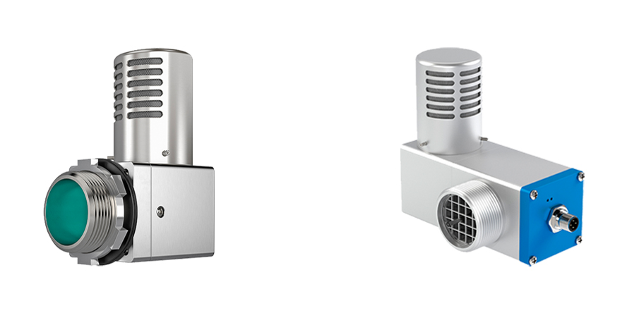
Enclosure protection vents for Bebco EPS® purge and pressurization systems
Despite the fact that purging is not required for dust applications, catastrophic system failure can still occur if excessive airflow enters the protective enclosure. Without an enclosure protection vent, the enclosure will most likely fail in the event of overpressure.
One of the requirements of an enclosure protection vent is the spark and particle barrier at the exhaust. Most likely, the purge flow or overpressure flow will escape into the hazardous area. Since electronic devices may be operating within the enclosure and these are ignition-capable, sparks generated within the enclosure cannot exit the enclosure into the hazardous area, therefore the spark barrier at the vent is required.
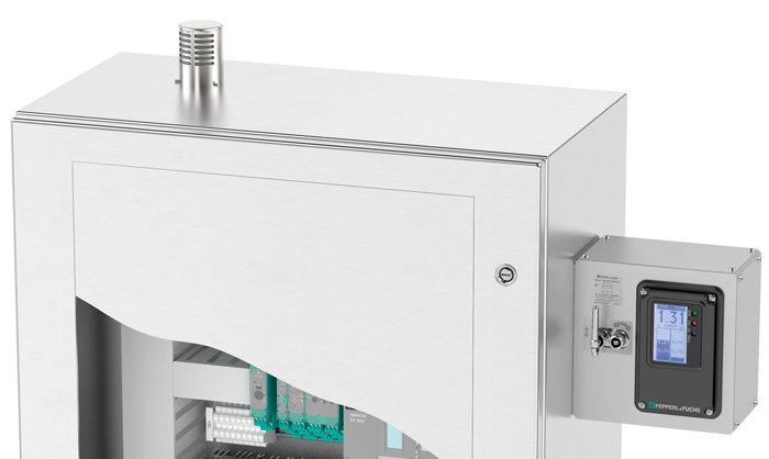
The 7500 purge and pressurization system with enclosure protection vent mounted on top of the housing.
Three Factors Determine the Enclosure Protection Vent Selection
The selection of an enclosure protection vent depends on the following parameters:
- The classification of the hazardous area, which is based on Class/Division or Zone
- The selected purge and pressurization control unit for your application
- The final vent selection depends on purge flow, enclosure pressure, and leakage
Types of Enclosure Protection Vents for Purge and Pressurization Systems from Pepperl+Fuchs
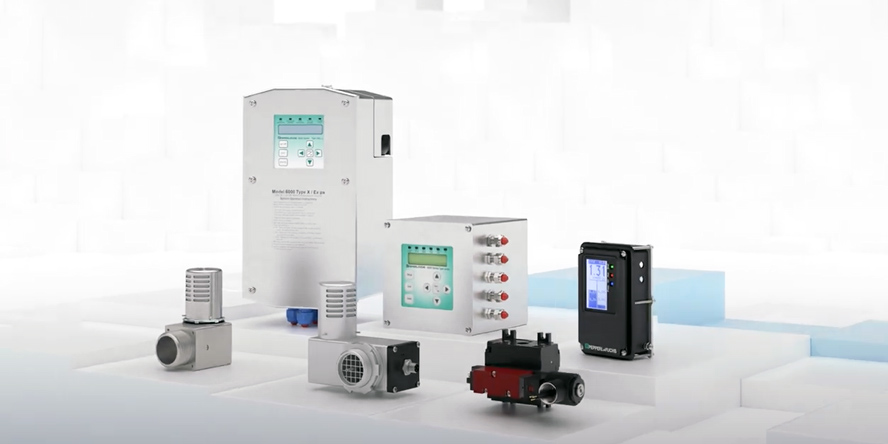
Pepperl+Fuchs offers various enclosure protection vents for its Bebco EPS® purge and pressurization systems.
EPV-6000 and EPV-6500 Enclosure Protection Vents
- The EPV-6000 is suitable for Type X/pxb purge and pressurization systems.
- The EPV-6500 is suitable for Type X/pxb and pyb purge and pressurization systems.
- Both vents are certified for Class I or II, Division 1/Zone 1 or 21.
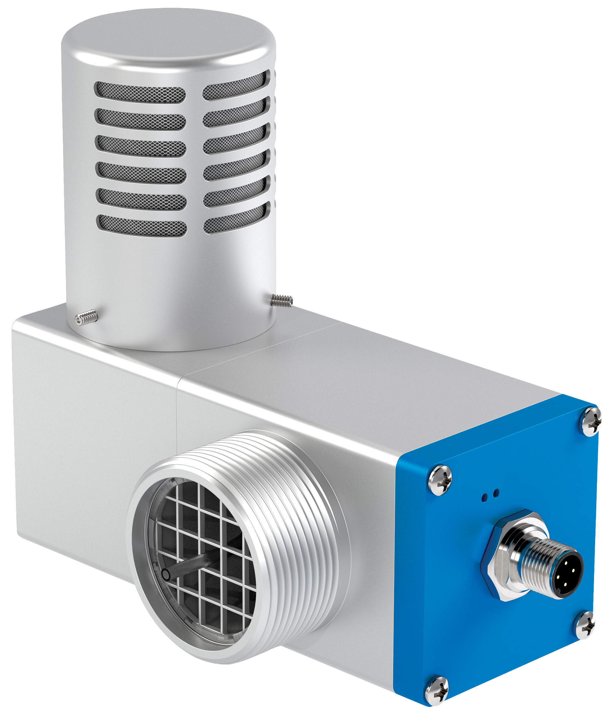
EPV-6000 / EPV-6500 enclosure protection vents certified for Class I or II, Division 1/Zone 1 or 21
The IEC60079-2 Standard requires that all purge systems in a Zone 1 application monitor flow at the vent exhaust. The EPV-6000 and EPV-6500 vents have an internal flow transmitter that measures the flow. They also have a differential pressure transmitter to indicate the enclosure pressure. Pepperl+Fuchs offers the only enclosure protection vent in the industry that digitally measures flow rate and pressure.
Both vents are designed to be secured to the enclosure with a locknut when mounted externally. For internal mounting, the structure is mounted to the enclosure with the vent body inside the enclosure and the cap on the outside.
EPV-7500 and EPV-5500 Enclosure Protection Vents
- The EPV-7500 and EPV-5500 vents are suitable for Type Y or Z/pzc purge and pressurization systems.
- They are certified for Class I or II, Division 2/Zone 2 or 22.
The EPV-5500 and EPV-7500 are very similar in design, with the exception that the EPV-5500 vent has an exhaust cap with two rows of slots, while the EPV-7500 has three rows of slots. This is the reason they have different purging flow rates. Neither vent has electronics because flow and pressure are measured by the 5500 or 7500 purge and pressurization system control units and the standards do not require flow measurement at the outlet. The vent opening and cap designs are the same as the EPV-6000 and EPV-6500 vents, therefore mounting is identical.
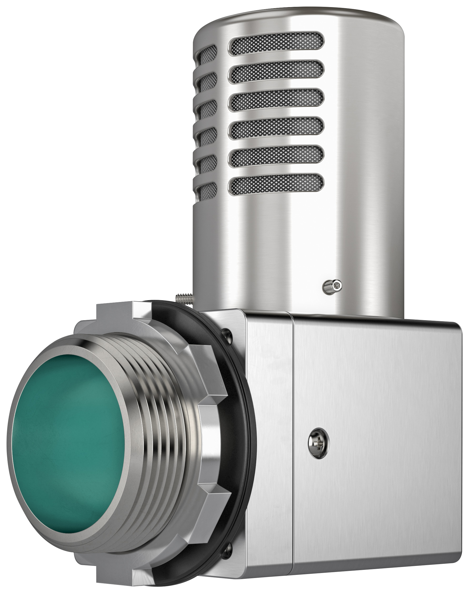
EPV-5500 / EPV-7500 enclosure protection vents certified for Class I or II, Division 2/Zone 2 or 22
The EPV-5500 and EPV-7500 are very similar in design with the exception that the EPV-5500 has an exhaust cap with two rows of slots and the EPV-7500 has three rows of slots. This is the reason they have different purging flow rates. Neither vent has electronics because flow and pressure are measured by the 5500 or 7500 control units and the standards do not require flow measurement at the outlet. The vent opening and cap designs are the same as the EPV-6000 and EPV-6500 vents, therefore the mounting is identical.
The EPV can be selected based on flow rate/enclosure pressure and leakage rate when pressurized. The vent type code includes options for this. For example, see the Pepperl+Fuchs nomenclature of the EPV-7500 vent, which is similar to the other enclosure protection vents.
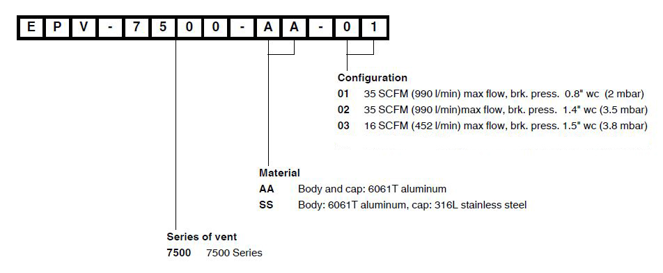
Nomenclature for EPV-7500 enclosure protection vent
Levels of Operation—the Three Phases of the Purging Procedure
During purging, the vents must open and allow overpressure/flow to escape from the enclosure. The NFPA496 and IEC60079-2 Standards require the free volume of the enclosure to be flushed out several times before the enclosure is considered free of hazardous gases. NFPA496 requires four volume changes and IEC60079-2 requires five volume changes. For motors, both standards require ten volume changes; however, the stator volume can be subtracted from the free volume for calculation purposes.
After purging or pressurization of the enclosure, the flow rate is reduced to compensate for leakage from the enclosure and vent. Although the vent is sealed, slight leakage through the flapper or plunger mechanism will occur.
If, during operation (pressurization) of the system, the enclosure pressure increases, the enclosure protection vent will begin to open and release the excess pressure. The point at which the vent starts to open is referred to as the breaking pressure.
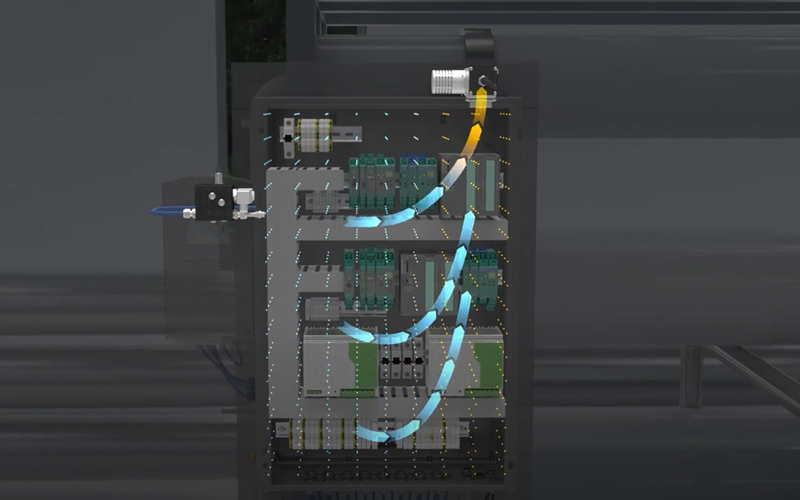
By purging an enclosure with high pressure air, the internal components are maintained and protected. The EPV provides pressure relief during the purge cycle.
Vent Flow Design Options
The mechanism for the flow through the vent is a flapper or plunger opening mounted inside the vent. The design depends on the values of the three parameters mentioned:
- Purge flow rate
- Enclosure pressure
- Leakage rate
The EPV vents are either a flapper or a plunger design and are held closed by a spring.
There are two versions of the flapper design: one spring or two springs hold the two flappers down to create a seal. In this design, the flapper is pressed down on the aluminum opening. The single spring design has the highest flow rate at the lowest enclosure pressure for purging; however, it has the highest leakage rate through the flapper for pressurization.
The plunger design has a spring and sits on an O-ring to provide the best seal for pressurization; however, it has the lowest flow rate and highest enclosure pressure during purging.
Download Technical White Paper: How to Select a Pepperl+Fuchs EPV
More Information
Subscribe to our newsletter and receive regular news and interesting facts from the world of automation.
